June 6, 2016 — 10 minutes read
iot nabaztag
Nabaztag/tag
- Updated: June 15th, 2016
- Created: June 6th, 2016
- Object: Detail what’s inside a Nabaztag/tag, with components references when possible.
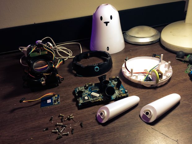
I’m obviously not the first one trying to recycle my Nabaztag. Previous dissections have been done by others so I will reuse what they have done and will keep it here as a reference for my own usage.
Most of the information on this page come from this guy, so thank you.
Pictures are from multiple sources (links at the bottom of this page) and I’ve made my own, mostly because I didn’t find pictures detailing the ears mechanism (DC motors, pulleys-belt and IR encoders).
You’ll notice my Nabaztag/tag’s plastic body turned a bit yellowish with the years, I’ll try to fix this with the Retr0bright chemical mixture later on.
Front view
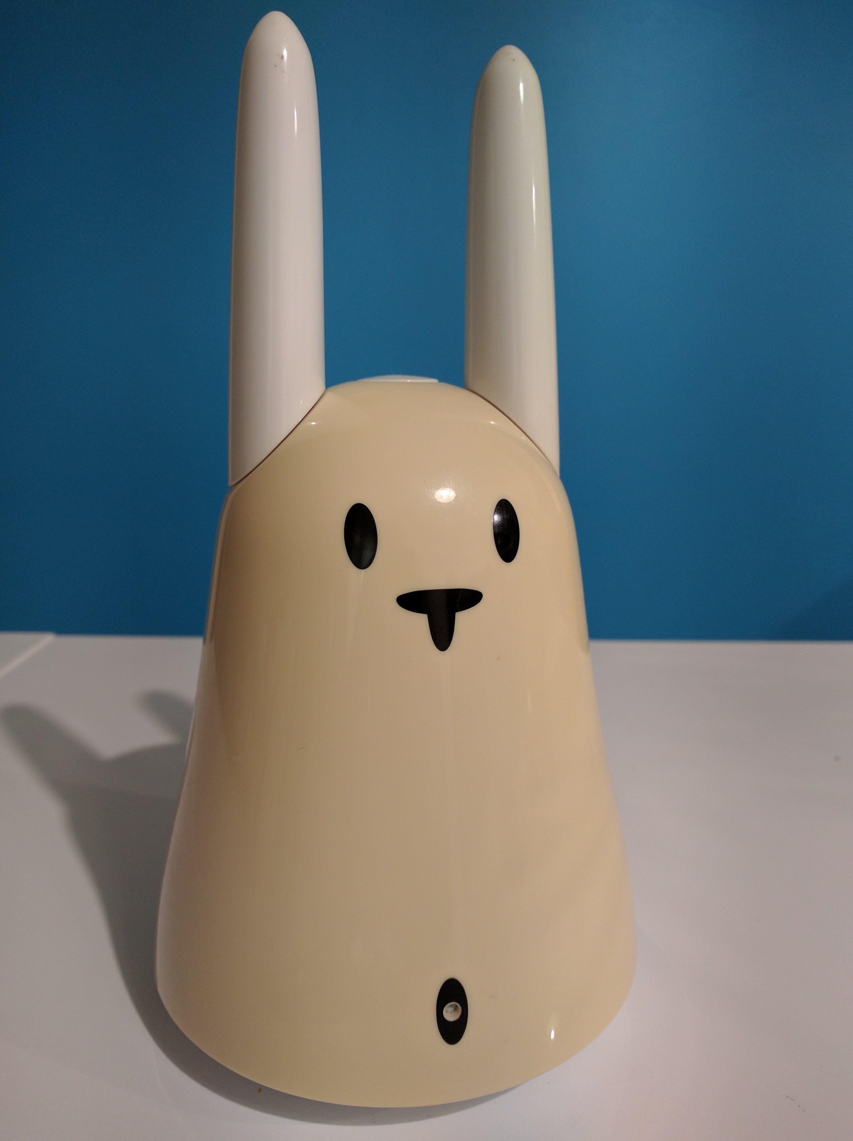
So from this point of view we can see (top/down):
- A button at the top;
- Two rotating, magnetic placeholders for the ears;
- 4 LEDs with directional cones;
- An RFID reader at the center, in front of the main board;
- A microphone at the base of the rabbit;
- The main board but I don’t care about this one.
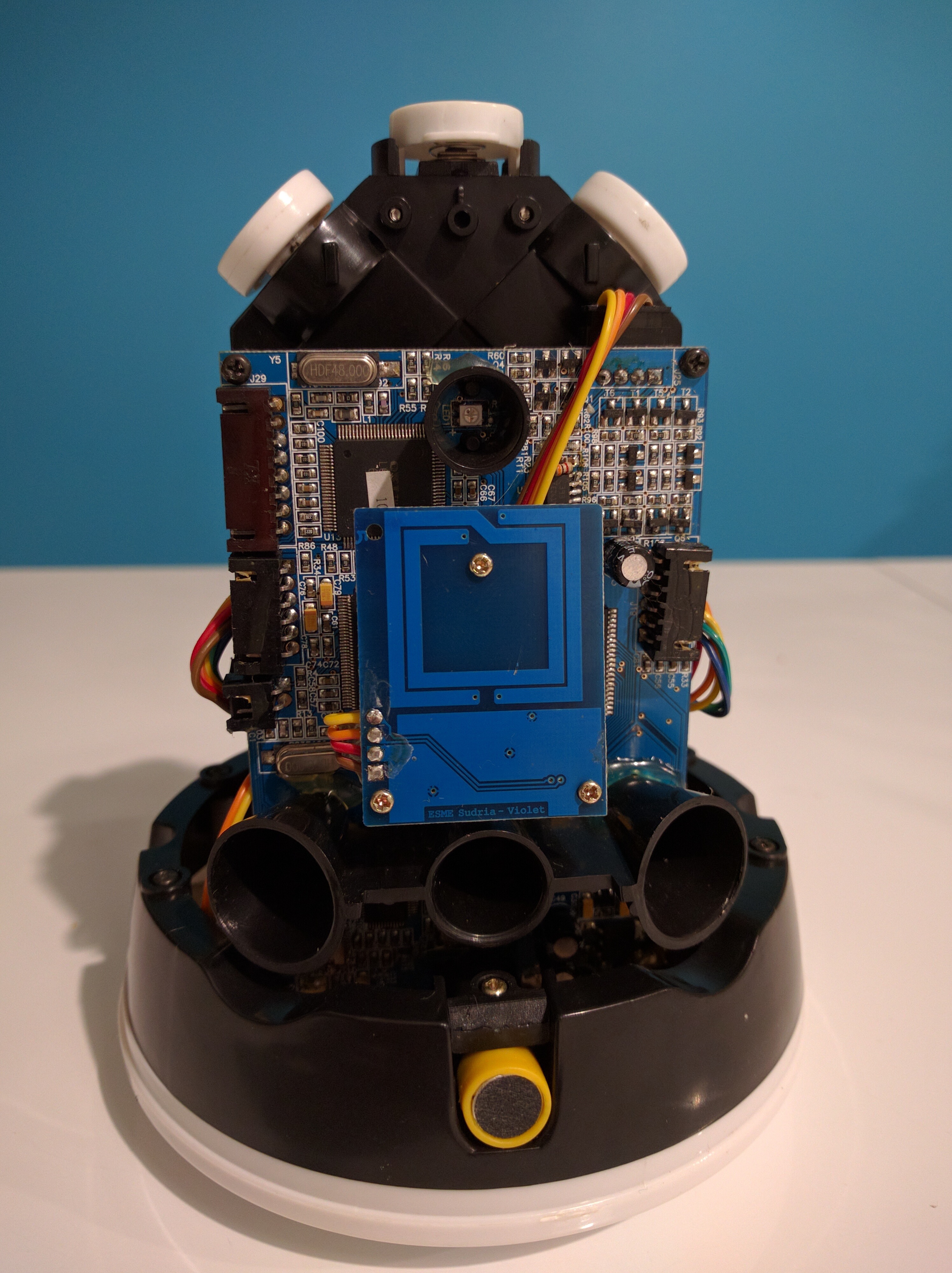
Back view
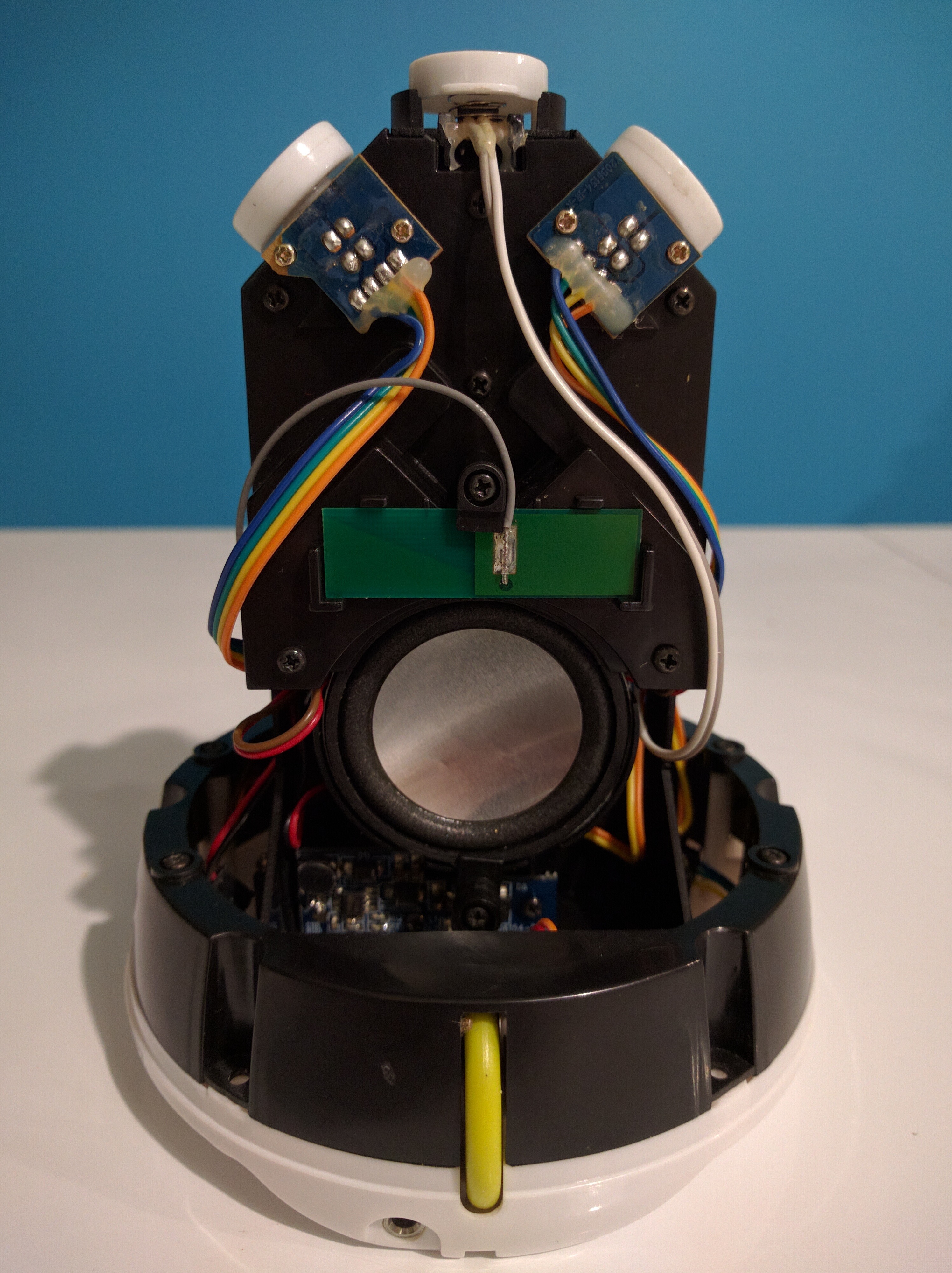
At the rear, we can see (top/down):
- Two IR encoders to control the rotation of the ears, at the top;
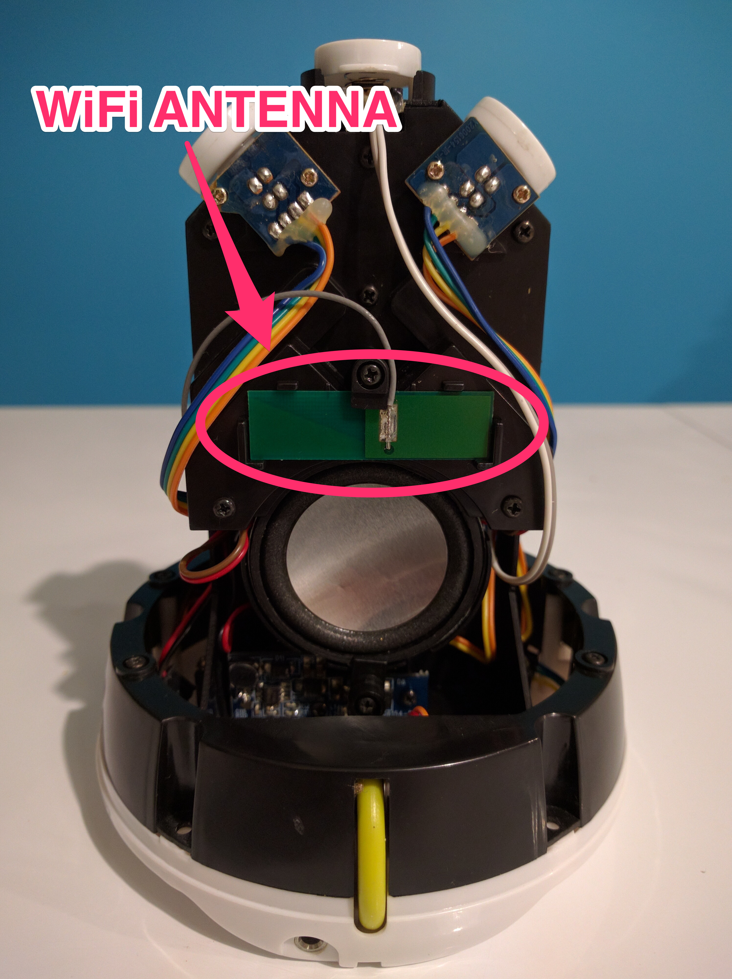
- The WiFi antenna at the center, in green;
- A loudspeaker a the center just under the WiFi antenna;
- The small card at the bottom is the “power adapter”;
- A scroll wheel;
- A 3.5mm phone connector (headphone jack).
The button
Will be reusable as is, it seems, so I don’t have much to say about this one.
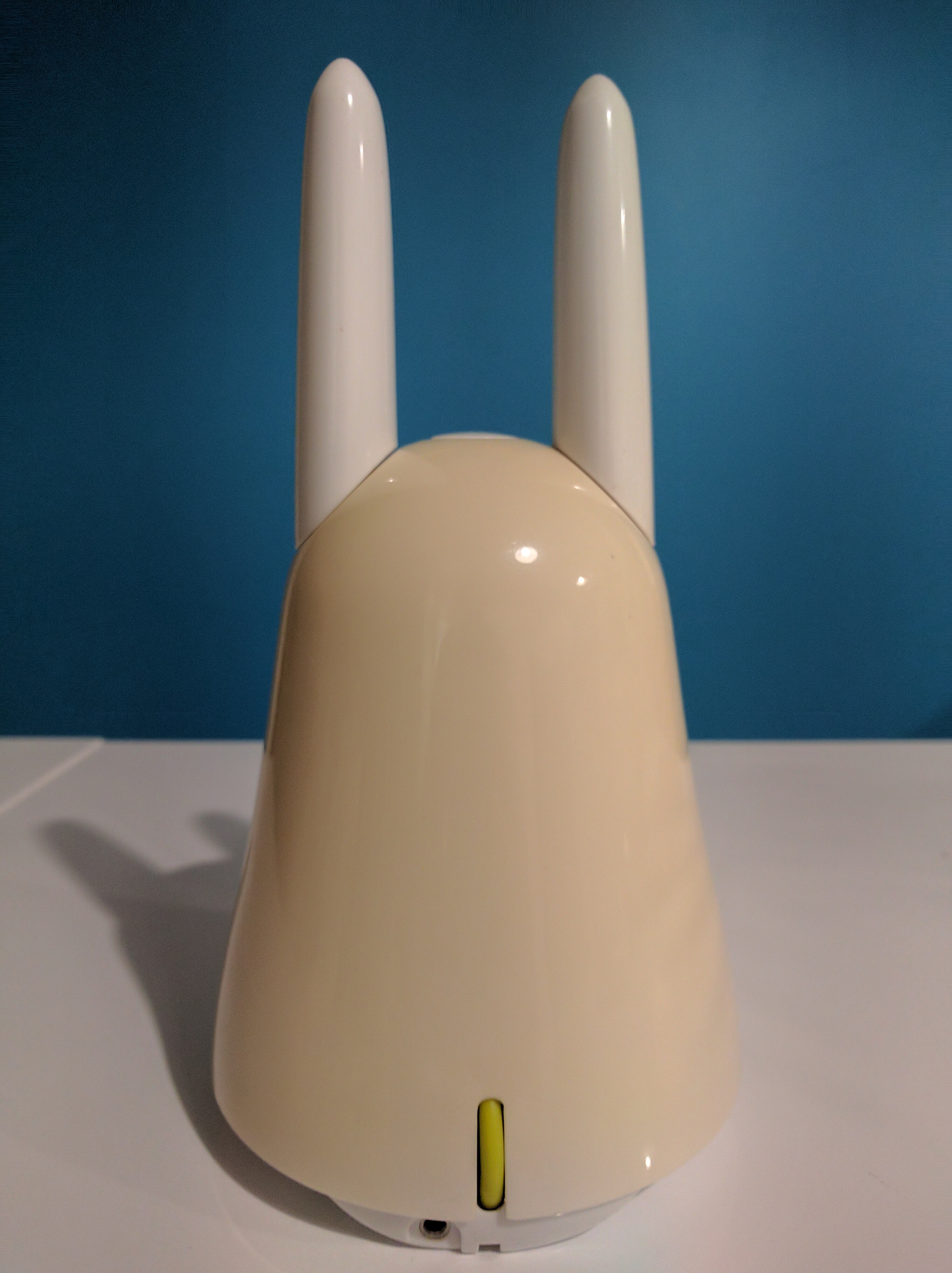
The ears
They are attached to the body via magnets and are really just two pieces of white plastic.
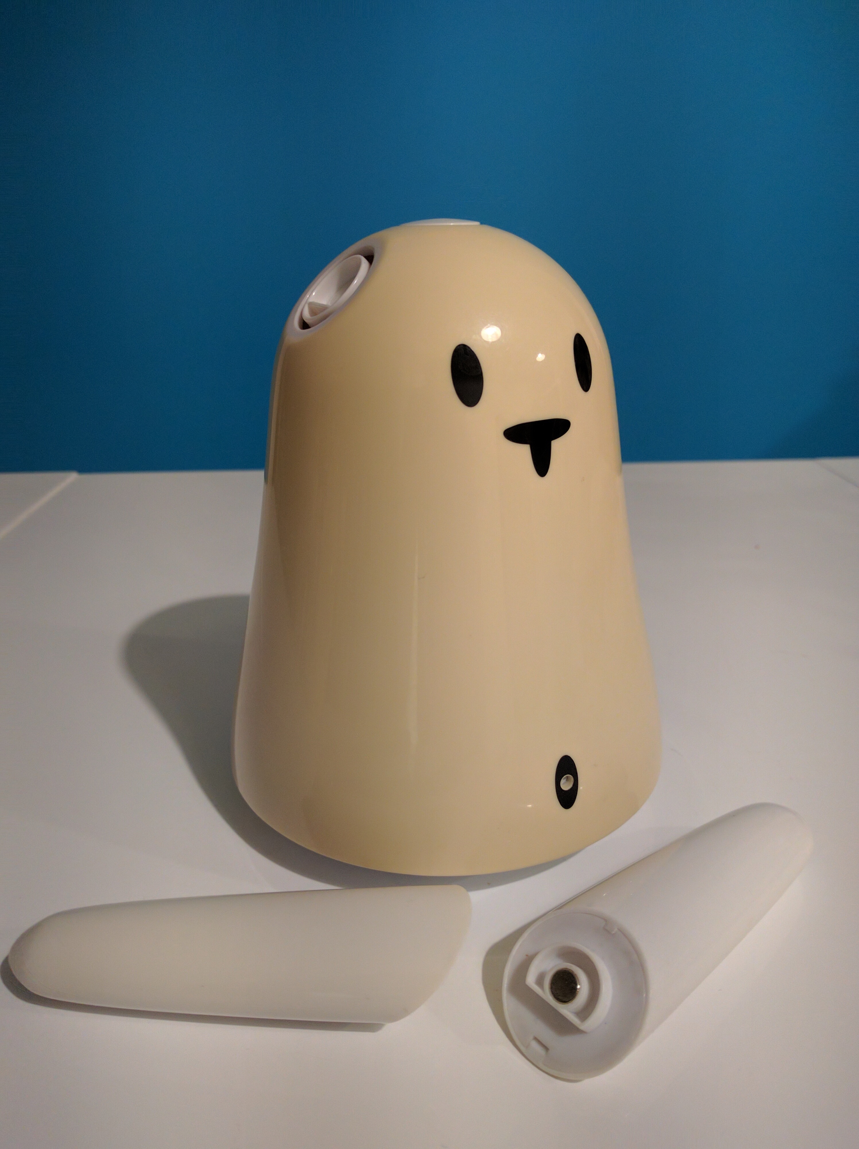
At some point, Violet or one of its successor, used to sell colored ears (with patterns and all) for fun and profit. I wonder where they did all go. Anyway.
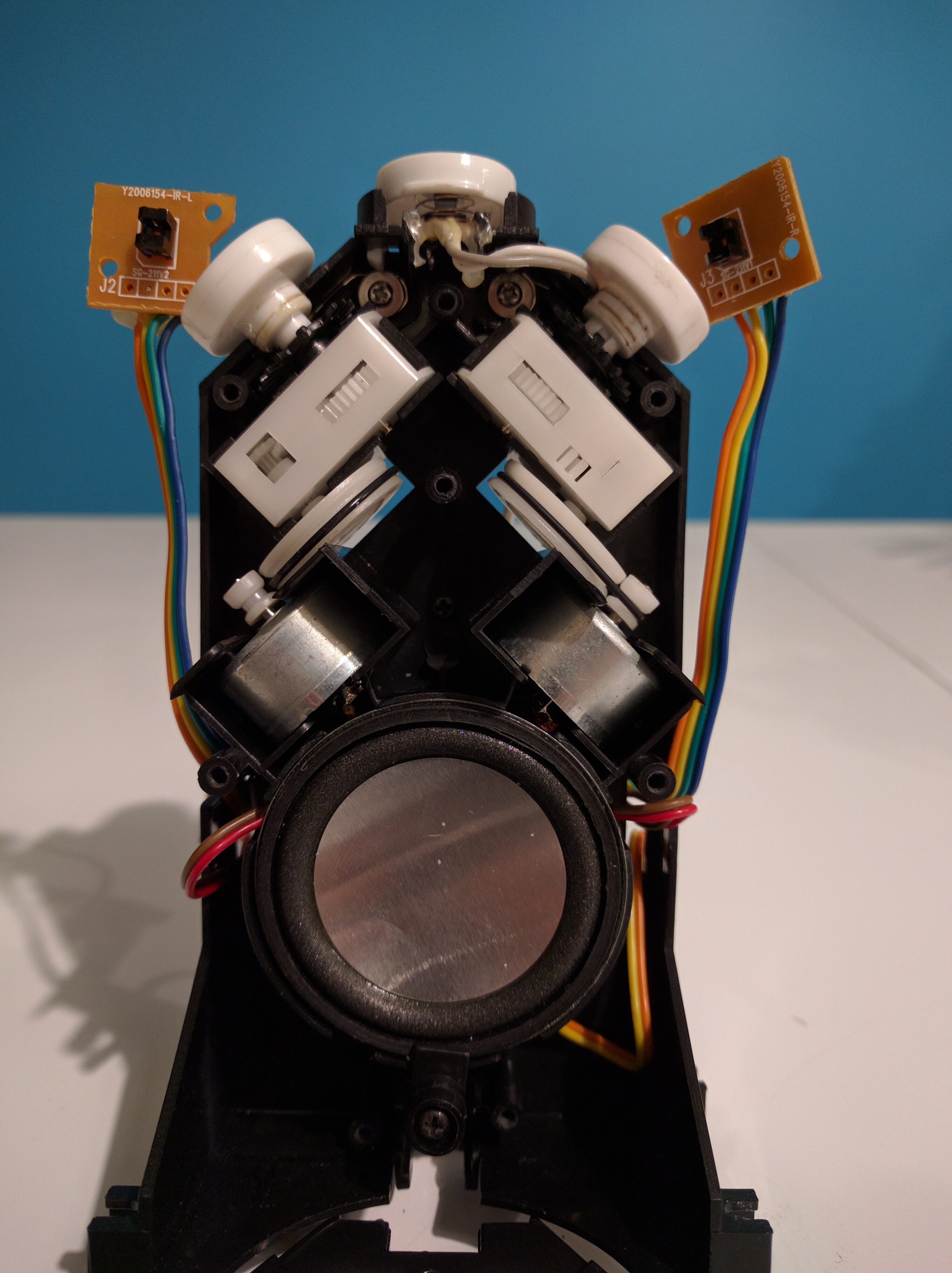
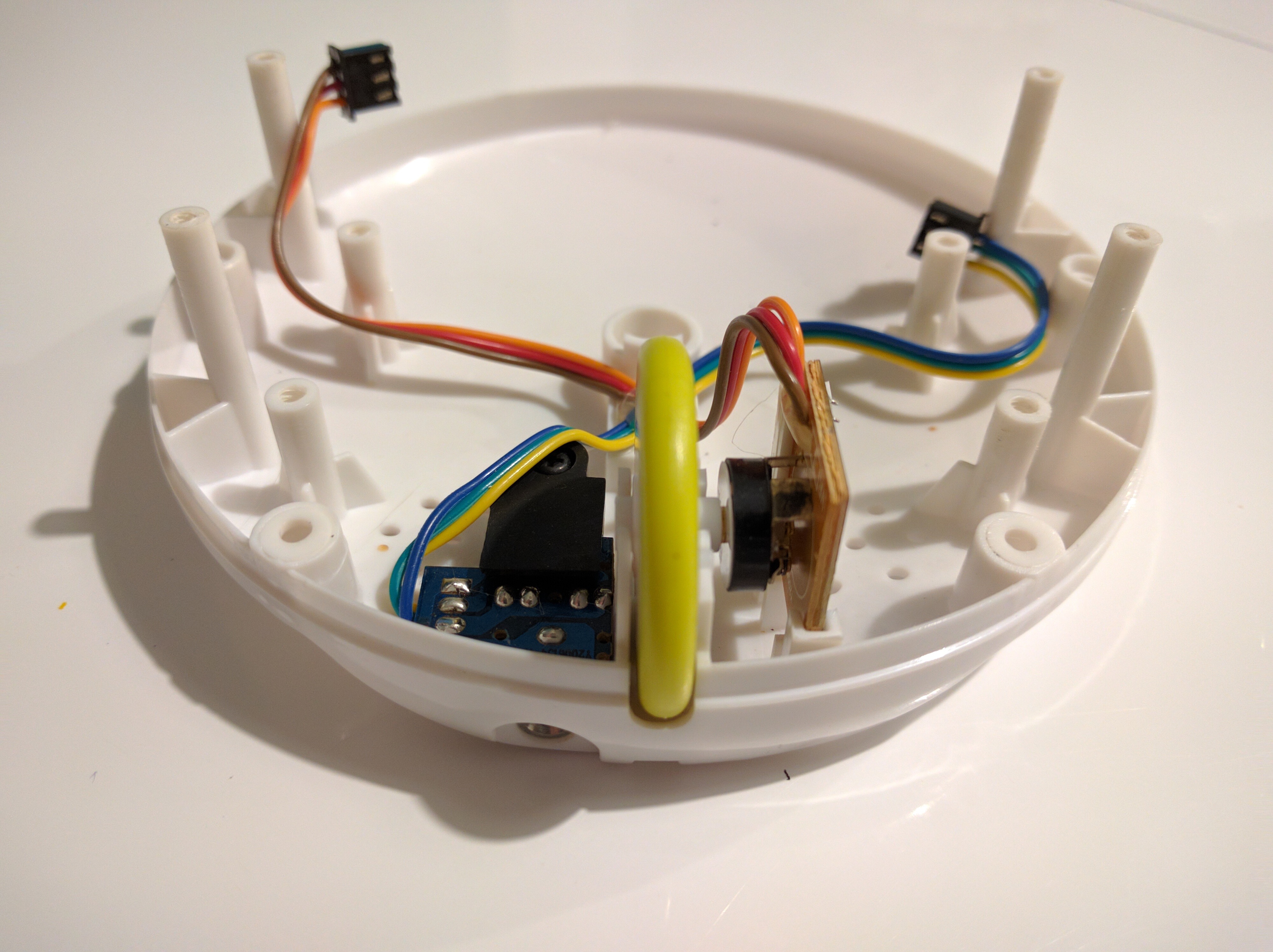
This is the internal view of the back of the rabbit once you’ve removed the black plastic case covering the ears mechanism.
You can see it consists of two “classic DC motors”, wired to the rotating pads of the ears (on top) via pulleys-belts.
The DC motors
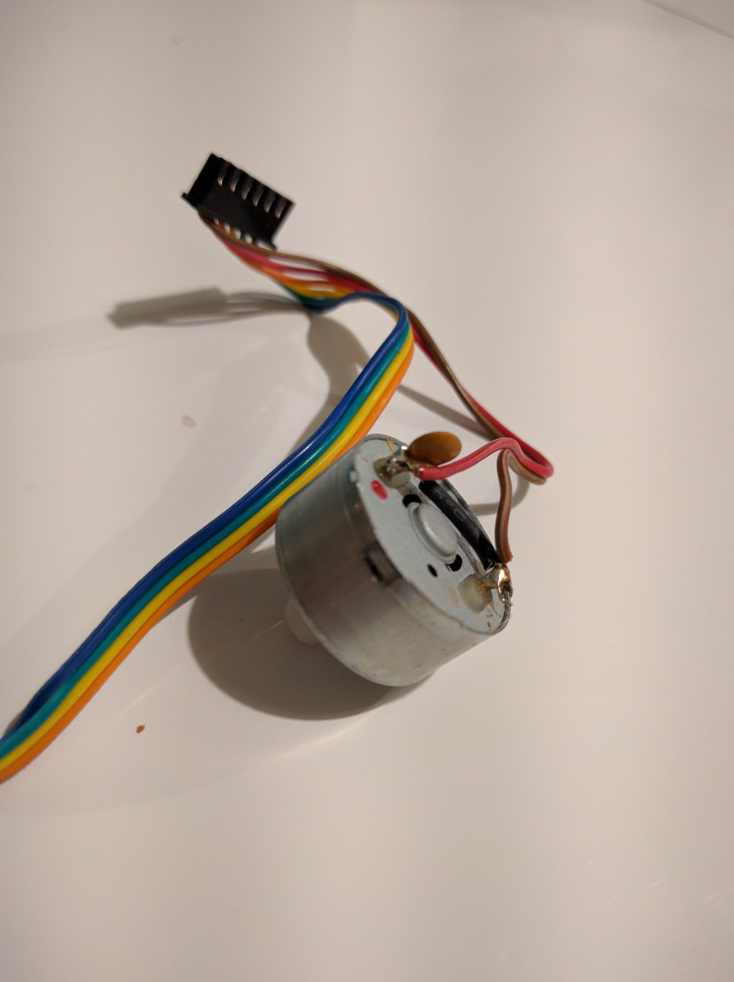
Plagiarizing Hack the Nabaztag, here’s a description of the DC motors:
The motor wires are BROWN and RED. If you connect one to GND and one to PWR, the ears will spin in one direction; if you swap them, they go in the opposite direction.
And:
If you want the ears to be bidirectional, you will have to implement an H-bridge - a hardware switch that reverses a motor’s polarity.
Thanks, this is exactly what we’ll do eventually.
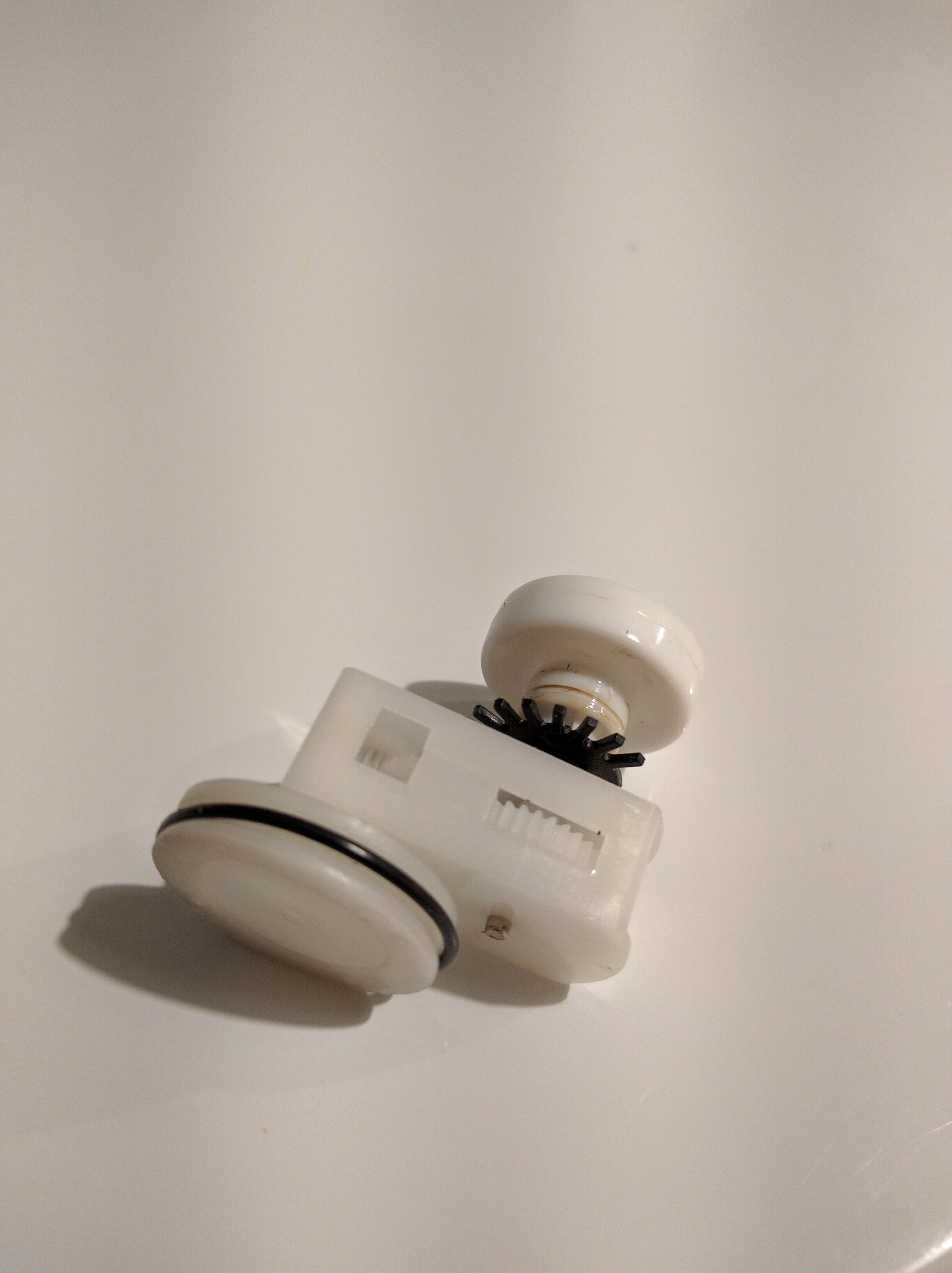
The IR encoders
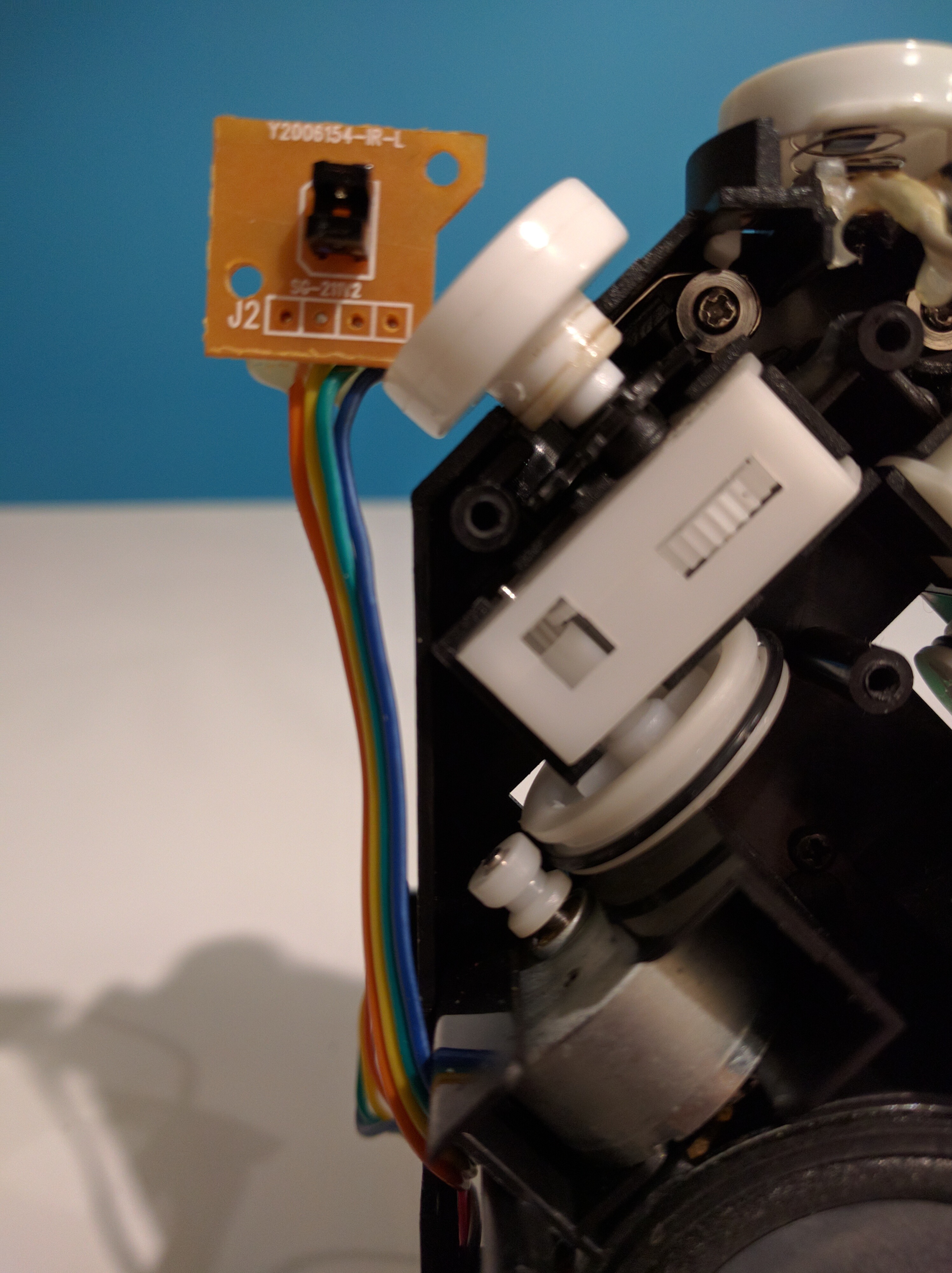
This time plagiarizing from Rabbity-Pi, here’s a description of the use of the IR encoder:
A IR encoder is used to control the rotation, a wheel with 20 tooth passes in front of the IR sensor. Actually 3 of those tooth are missing (in order to detect the absolute position). The Nabaztag is doing a full rotation of the ears when booting in order to initialise the positioning.
Numbering each teeth from 0 to 19, ear is vertical when teeth number 3 is in front of the sensor, and horizontal when it is teeth number 13.
And from Hack the Nabaztag:
Each of the little blue chips has a small optical encoder on it: an IR LED and a receiver that senses it. As the ear turns, a gear’s teeth pass between the LED and receiver, and turn it ‘on’ and ‘off’. The gear is missing one single tooth, so the encoder knows: when its signal does NOT get interrupted by the gear’s teeth, the ear is pointing forward. On tooth 3, ears point up; on tooth 13, they are horizontal.
I’m a total electronic beginner and if you too, I’ve googled around and found this great video on How an Encoder Works.
LEDs
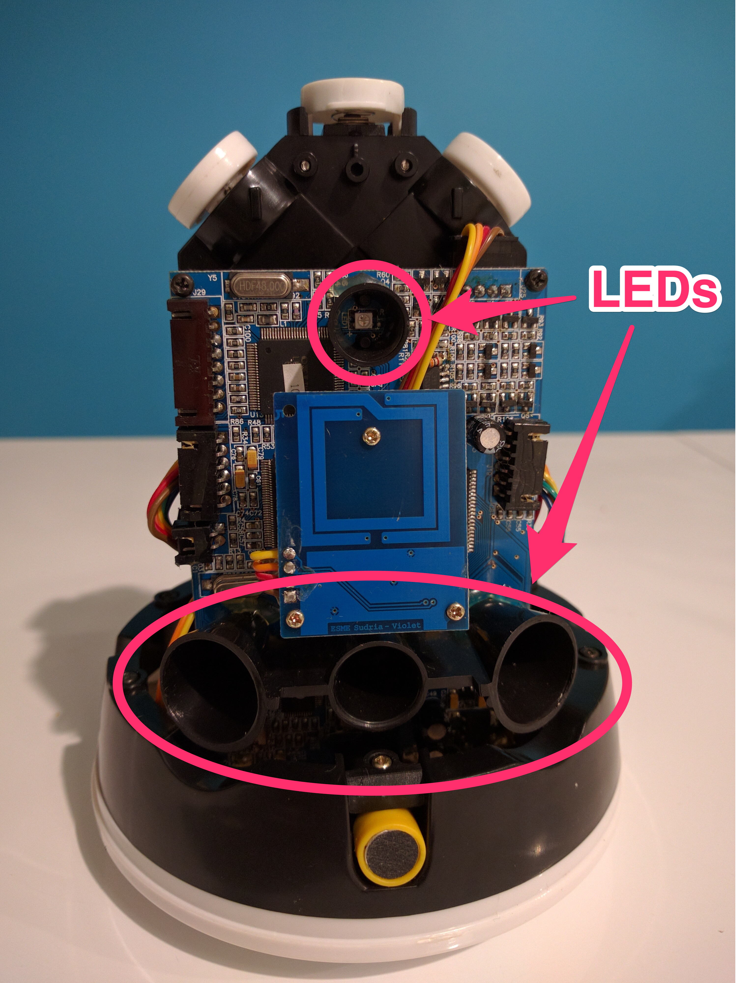
On this picture we can see four directional cones to lead the LEDs light onto the translucent case.
The LEDs are soldered onto the board, and what you cannot see on this picture (and I forgot to take another one, duh) is that there is a fifth LED at the bottom of the main board, whose cone is aimed toward the bottom of the rabbit, to give some sort of “ambient light”.
I don’t want to start “doing electronics” by having to identify components and unsolder them, so I just won’t reuse the LEDs and experiment with simpler ones.
RFID
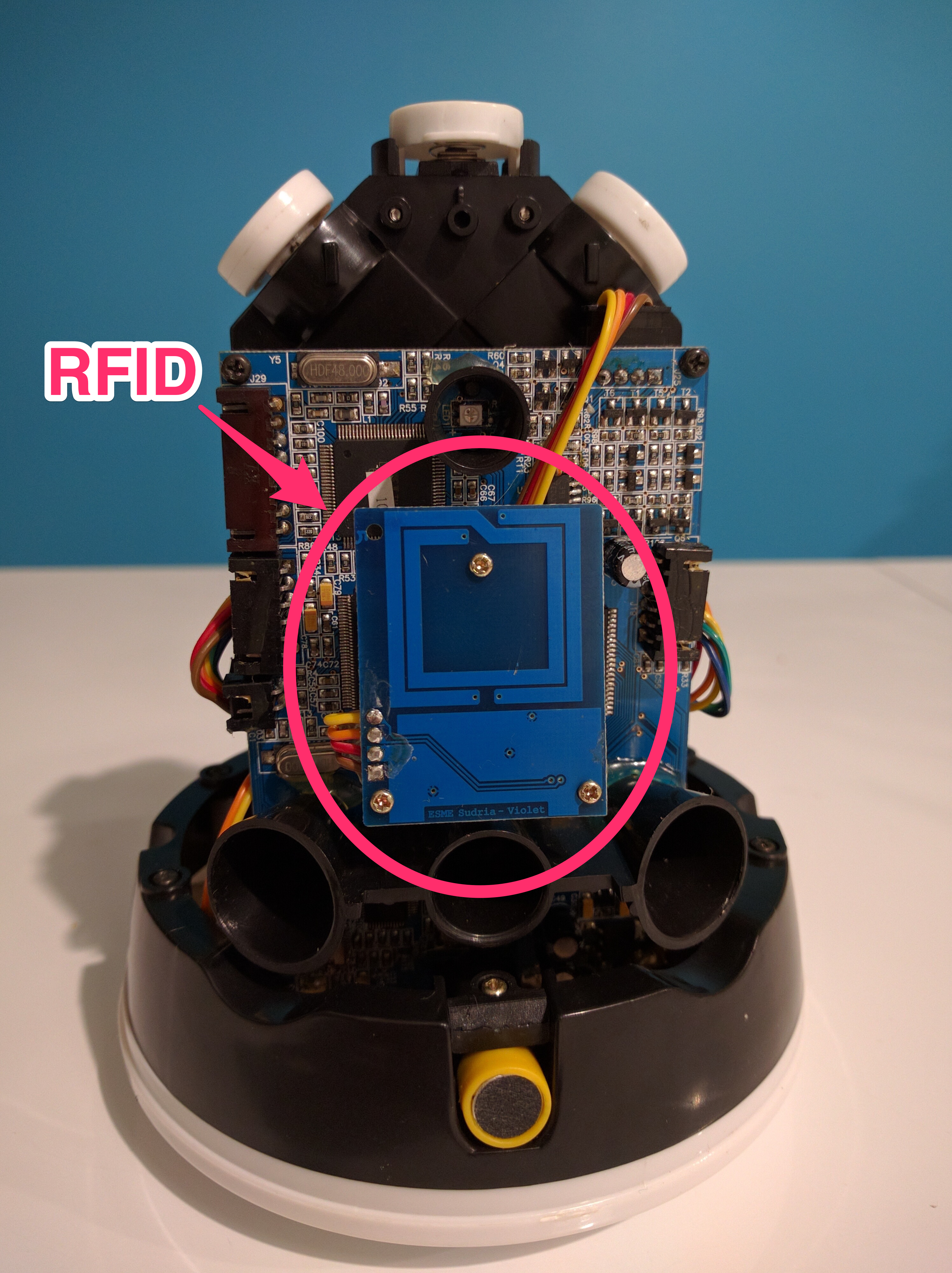
The RFID reader is also visible on the front picture, right at the center, between the LED cones and in front of the main board.
Nabaztagtag (Nabaztag v2) Dissection has more detailed information as he tried identify each component of the RFID reader. I am not going to use the RFID reader at first, and I can’t decide which technology (RFID, NFC, Bluetooth Low Energy?) I will use eventually, so I won’t try to reuse it either.
Microphone
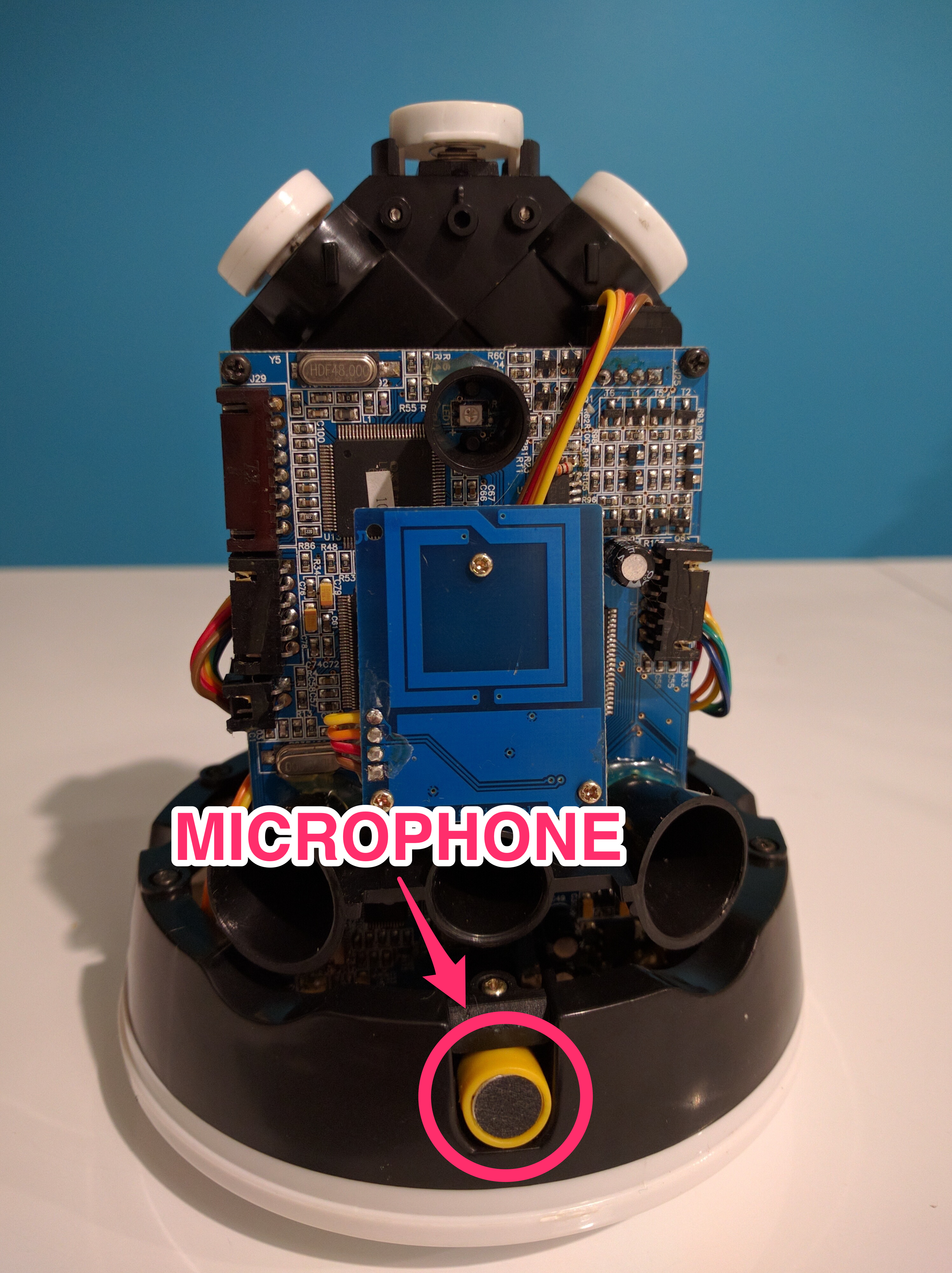
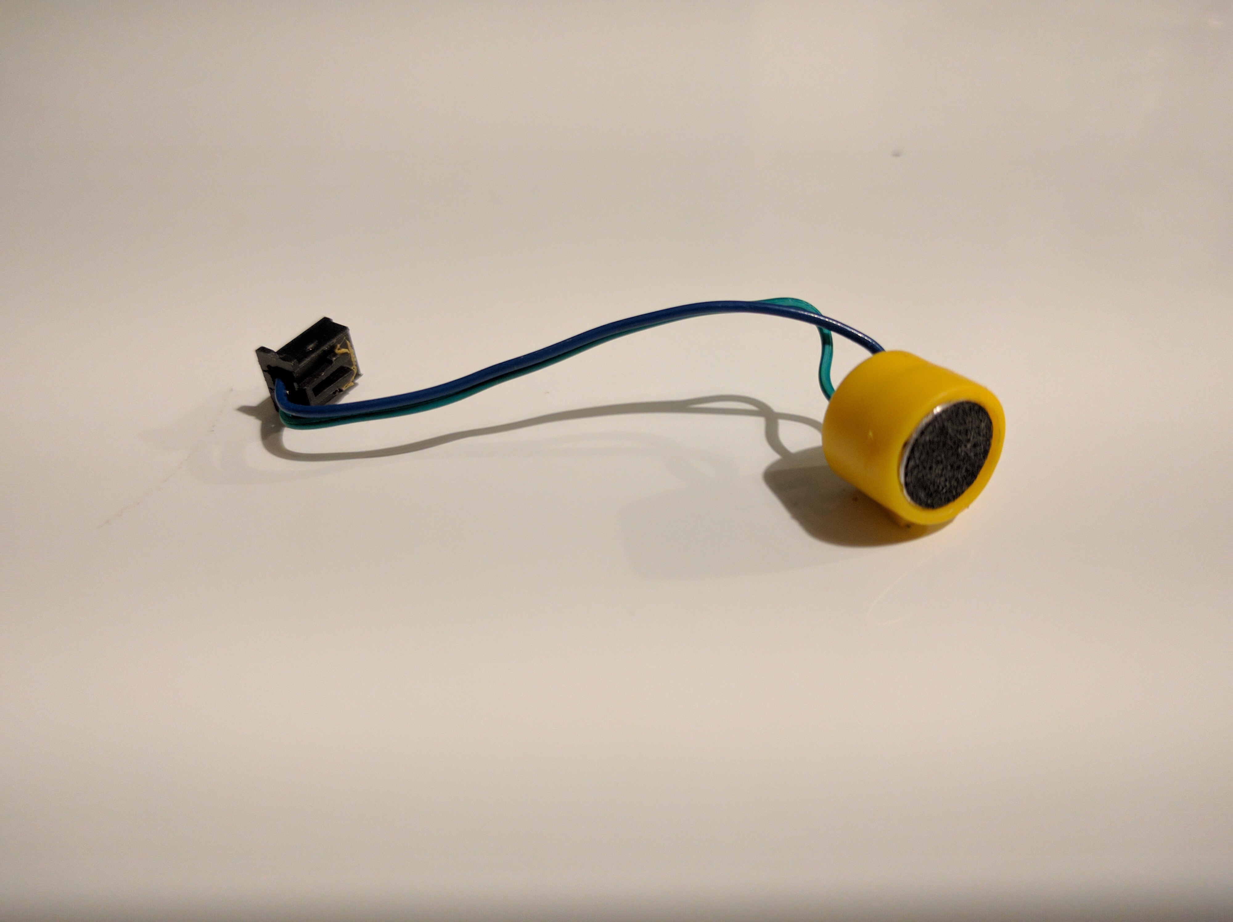
I do not know if I will make use of the microphone “as is” yet. Maybe I will have to replace it, be it for compatibility reasons or sound quality.
In RabbitPi, MisterM has used a Pi camera in his project to put where the Nabaztag/tag’s microphone and Karotz (Nabaztag V3) camera used to stand. And for the microphone, he used a webcam’s microphone.
Although he hacked a Nabaztag V1 which does not have a microphone already, whereas my V2 has one, I have to admit that I’m very tempted to do the same thing (with the Pi camera). Plus I will not have to drill a hole, maybe just make it larger.
WiFi
The WiFi capabilities is added via two components as it seems, a wireless module attached to the back of the main board, and a WiFi antenna at the rear of the rabbit.
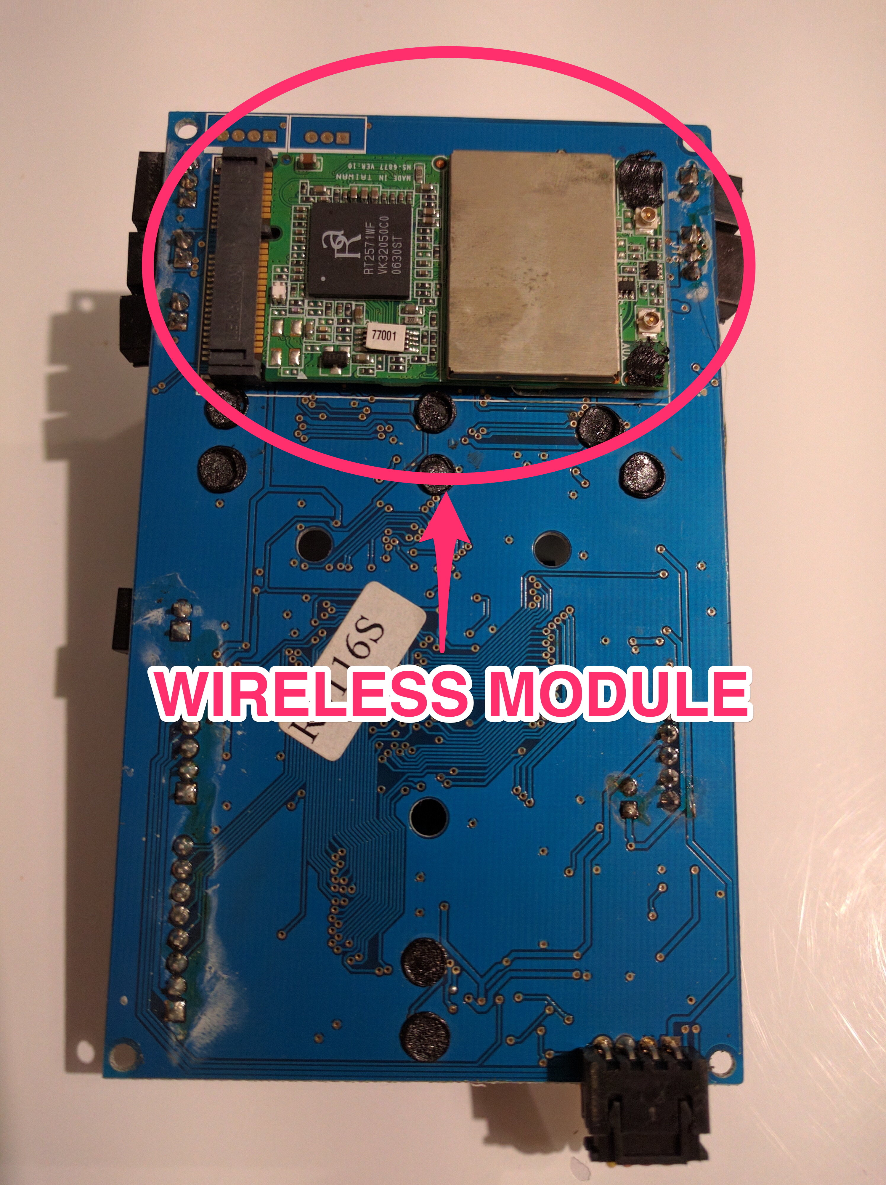
Again, at this point I think I am just not going to use this setup at find a standalone WiFi dongle that fits into the rabbit’s body. There are some funny hacks out there, and also an interesting project to keep an eye on.
Loudspeaker
The loudspeaker is clearly visible at the center of the rabbit’s back. To me it looks like a basic sound speaker, nothing to be afraid of.
In RabbitPi, MisterM has used a phillips soundspeaker in place of the original one.
I’m not sure I understand why, plus it looks like it needs a battery instead of just being powered by the Nabaztag itself. But maybe I just missed an important information while reading his project.
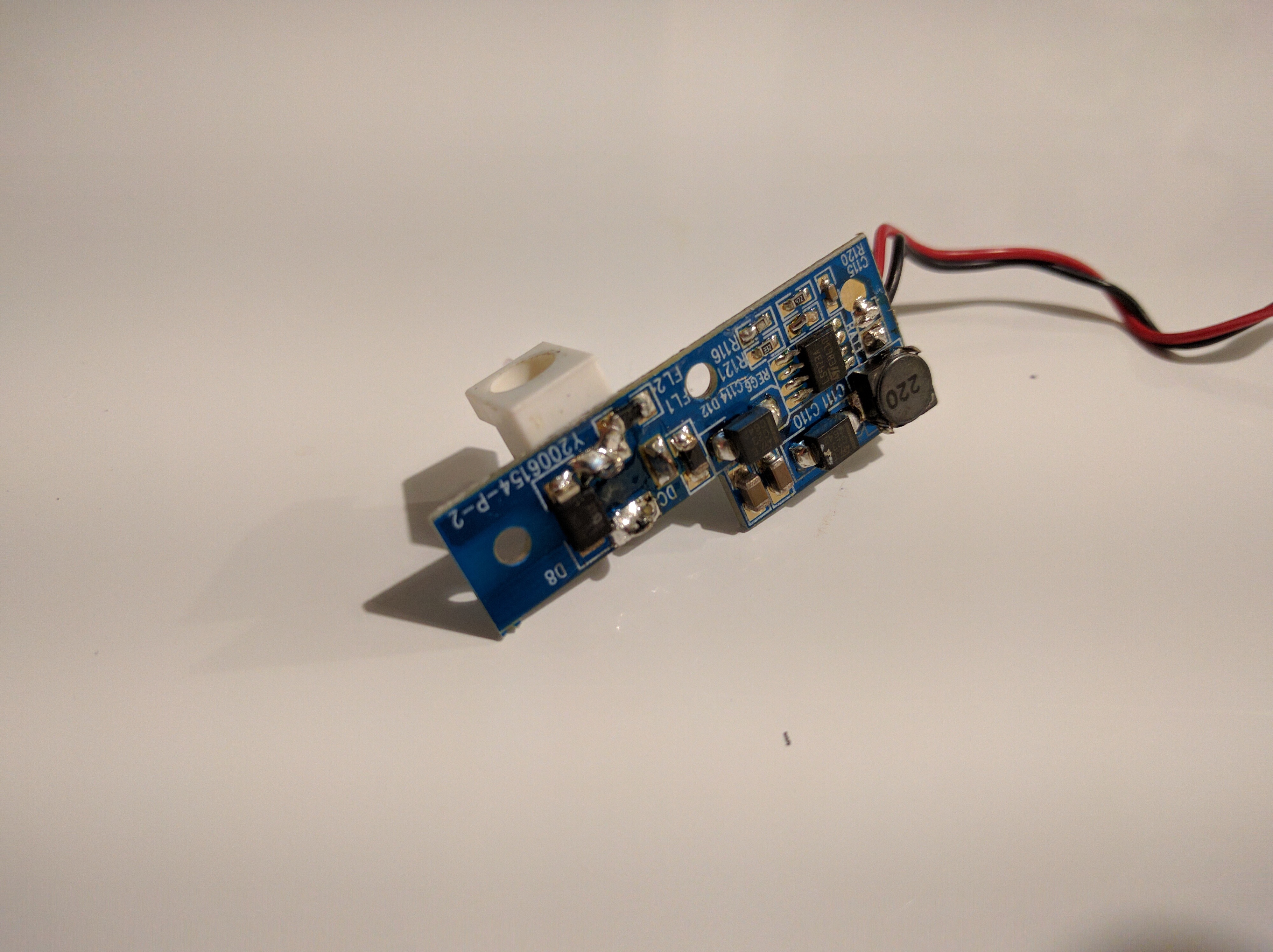
Power
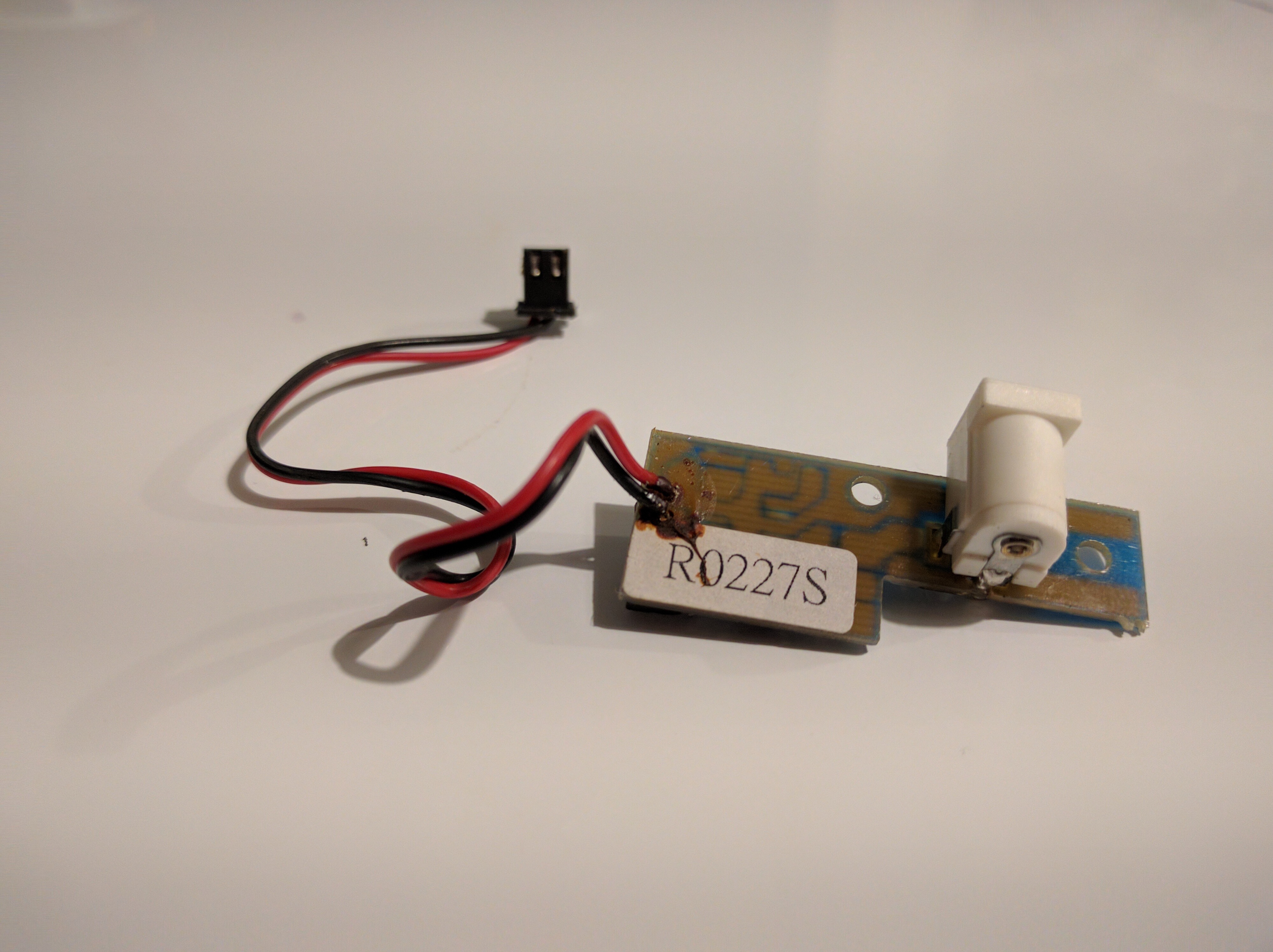
I’m a bit lost, here.
This is the power supply of the Nabaztag/tag, which comes with a cord that I have lost, I mean I think did. And even if I still have it, somewhere, I’m not quite sure what to do about it because I’m pretty sure this needs work to make the voltage and stuff in line with what the RaspberryPi needs/can sustain.
Rabbity-Pi summarizes my thinking almost accurately:
At first I wasn’t interested in re-using the Nabaztag power system but as it provides a removable connector that may be easily connected to my electronic board, I may reuse it. At least to power the motors, and maybe the Raspberry-Pi itself if the voltage and other characteristics are suitable.
I had planned to run the motors from a usb power bank so that I’d only need a single power plug, but this turned out not to have enough grunt, it wouldn’t even light up the “Working” led on the HAT. I decided instead to use a DC power adaptor to run the HAT and ears, I conveniently had one of those universal ones with interchangeable tips handy. What I didn’t have was a DC socket to connect the adaptor to the HAT. […] I remembered from the teardown that the Nabaztag’s original power lead was a standard DC plug - therefore I could just re-wire the original power socket to the HAT - neat! In the end I also re-used the original Nabaztag power supply, as it provided just the right amount of power.
I’m too much of a beginner to know at first sight what I can/cannot do with a piece of electronics. My guts tell me that I can reuse this (and me wants to reuse this), but I will see what I can do with it when I’ll really begin messing with eletronics and get my hands dirty on some basic techniques.
Sound
Scroll wheel
I definitely want to keep this and use it for either sound volume control or other interaction.
Again according to Hack the Nabaztag:
The scroll wheel is a potentiometer: it measures voltage, which changes as we rub the ‘wiper’ up and down. This is an analog input, which the Teensy will convert into a number between 0 and 1023.
He’s talking about a a Teensy because it’s the microcontroller he’s using. I think my RaspberryPi also has one or two analog inputs (need to check), and I also think it is possible to add external ones in the mix, so no blocker here, just need to wire everything correctly.
Closing
The following are two parts of Hack the Nabaztag that I quote here for reference, I feel like they will prove useful.
This section is called “Step 10: Wiring it up, for reals.” and it summarizes some wiring order instructions and voltage information:
At this point, if you’ve been working on a breadboard, it’s time to take it all apart and re-solder it permanently. This is going to be a MESS of wires, so pay close attention to where you route things - there’s less space in that rabbit than you think!
My recommendation: take your break-apart headers, and solder your wires to them first, so that they are like breakaway extensions from the existing wires. Do everything but the H-bridge; that’s a special case. Once you have extension wires on all 5 sets (head, scroll, LEDs, and two ears), temporarily mount the H-bridge and the Teensy somewhere on your cardboard block. Route wires as carefully as you can into their final places, and solder them into the Teensy. Finally, connect all the H bridge wires to the motors and the Teensy.
As a review, these are the pins, as I’ve placed them:
- Head button 14 (digital input)
- Scroll wheel 21 (analog input)
- LEDs 2 (output)
- Left motor enable 7 (output)
- Left motor reverse 8 (output)
- Left motor forward 9 (output)
- Right motor enable 10 (output)
- Right motor reverse 11 (output)
- Right motor forward 12 (output)
- Left encoder 18 (analog input) (with resistor –> GND)
- Right encoder 19 (analog input) (with resistor –> GND)
The power should be:
- Head: NONE
- Scroll: 3.3V
- LEDs: 5V
- H-Bridge: 5V
- Encoder BLUE wires (with resistors): 5V
- Encoder YELLOW wires: 3.3V
… and you should have 6 wires going to GND.
This part is called “Step 11: Putting the Bunny back together.", and its name is pretty self explanatory:
Once you have all the wires soldered and heat-shinked, it’s time to wrap up.
First, make sure you’ve removed the existing power jack from the base of the black column, then thread your USB micro cable through the white base. If it doesn’t fit, shave some plastic off the cord’s head until it does. Plug it into the Teensy, and you’re set for powering and updating your new Bunny.
Screw the black column back onto the white base. You don’t need the black ring around the base anymore (though you can put it back if you like).
Gently wiggle the white case over the electronics and back into place. This might take a while. Just be patient - press wires out of the way, shave off more cardboard, add tape where needed - until it all fits again. It’s important to get the alignment right, or the ears will get stuck against the body. If you run into this problem, place a thin washer-magnet between the ear and the socket to give the ear some extra clearance.
Put the screws in, and you’re done - at least, with this part.
Links
Pictures and information (really, all of it) courtesy of:
- Nabaztagtag (Nabaztag v2) Dissection
- Cracking open the Nabaztag Wi-Fi rabbit
- Rabbity-Pi
- Hack the Nabaztag (Instructables)
- RabbitPi (Instructables)
This blog uses Hypothesis for public and private (group) comments.
You can annotate or highlight words or paragraphs directly by selecting the text!
If you want to leave a general comment or read what others have to say, please use the collapsible panel on the right of this page.